206
Tensión nominal:
0,6/1 kV
Norma diseño:
UNE EN 50525-2-11
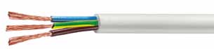
Designación genérica:
HO5VV-F
WIREPOL GAS
CARACTERÍSTICAS TÉCNICAS
DIMENSIONES, PESOS Y RESISTENCIAS (aproximado)
Número
de
conductores
x sección
mm
2
Espesor de
aislamiento
mm
Espesor
cubierta
mm
Diámetro
exterior
mínimo
mm
Diámetro
exterior
máximo
mm
Peso total
kg/km
Resistencia
del
conductor
a 20ºC
W
/km
Intensidad
admisible al
aire (1)
A
Caída de tensión V/A
km (2)
cos
f
= 1
cos
f
= 0,8
HO5VV-F
2 x 1
0.6
0.8
5.9
7.
5
65
19,5
8,7
43,13
34,62
2 x 1.5
0.7
0.8
6.8
8.6
85
13,3
16,5
28,84
23,22
2 x 2.5
0.8
1
8.4
10.6
130
7
,98
23
17
,66
14,25
2 x 4
0.8
1
.1
9.7
12.1
180
4.95
31
10,99
8,91
2 x 6
0.8
1.2
10.8
13.5
225
3.3
40
7
,34
5,99
3 G 1
0.6
0.8
6.3
8
80
19.5
8,7
43,13
34,62
3 G 1.5
0.7
0.9
7.4
9.4
110
19.5
16,5
28,84
23,22
3 G 2.5
0.8
1.1
9.2
11.4
165
13.3
23
17
,66
14,25
3 G 4
0.8
1.2
10.5
13.1
225
4.95
31
10,99
8,91
3 G 6
0.8
1.4
11.9
14.8
300
3.3
40
7
,34
5,99
4 G 1
0.6
0.9
7.1
9
100
19.5
8,7
3
7,5
1
30,11
4 G 1.5
0.7
1
8.4
10.5
135
13.3
15
25,08
20,19
4 G 2.5
0.8
1.1
10.1
12.5
200
7
.98
21
15,36
12,39
4 G 4
0.8
1.4
11.5
14.3
275
4.95
27
9,55
7,
75
4 G 6
0.8
1.4
13.1
16.2
365
3.3
36
6,38
5,21
5 G 1
0.6
0.9
7.
8
9.8
120
19.5
8,7
3
7,5
1
30,11
5 G 1.5
0.7
1.1
9.3
11.6
170
13.3
15
25,08
20,19
5 G 2.5
0.8
1.2
11.2
13.9
250
7
.98
21
15,36
12,39
5 G 4
0.8
1.4
13
16.
1
355
4.95
27
9,55
7,
75
5 G 6
0.8
1.4
14.3
17.
7
465
3.3
36
6,38
5,21
(1) Instalación en bandeja al aire (40 ºC).
PVC2 con instalación tipo C columna 8 (2x, 3G).
PVC3 con instalación tipo C columna 6 ( 4G, 5G).
(Ver página 28).